How a complete centrifugal feeding system works
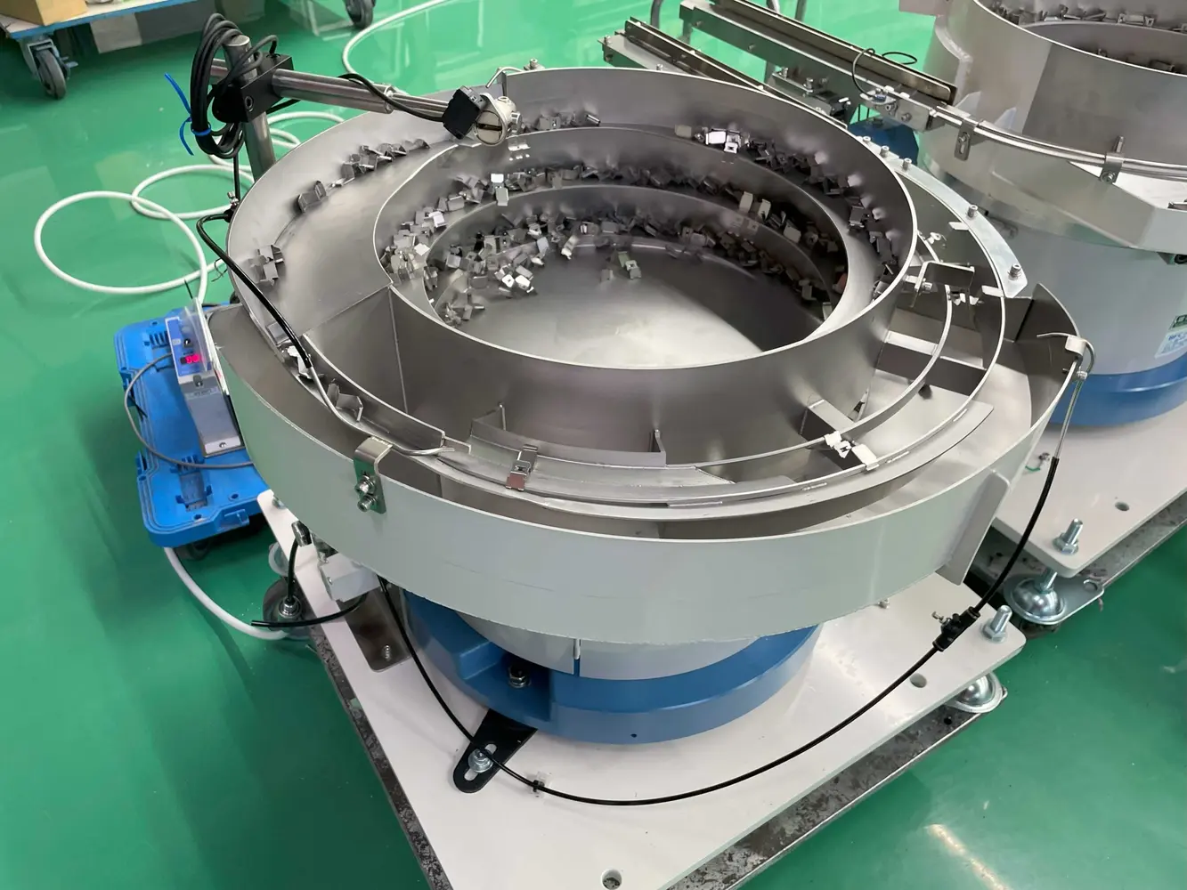
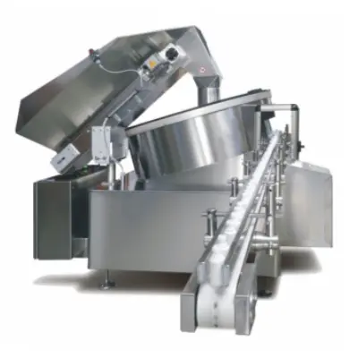
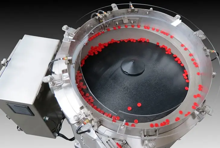
The centrifugal bowl is only one part of a dependable production solution. A regulated bulk supply keeps the working level stable. The rotating disc separates components and transfers them towards the selection track. Mechanical features recognise usable orientation, while unsuitable presentations return to the bowl without interrupting flow.
Accepted parts then enter a controlled outfeed. Accumulation provides a buffer, sensors manage demand and an escapement releases one component when the receiving machine is ready.
Core elements of a centrifugal bowl feeder
Bulk hopper or elevator
Stores production quantity and replenishes the feeder in measured doses. Level sensing prevents both starvation and overfilling.
Rotary disc and bowl
Disc profile, surface, rotational speed and bowl geometry are chosen to separate the part without unstable circulation or avoidable marking.
Orientation tooling
Guides, rails, wipers, air jets and selectors exploit repeatable component features. The objective is robust orientation across dimensional and finish variation—not one ideal sample.
See how component orientation and the accepted presentation should be defined.
Outfeed track and buffer
The outfeed maintains orientation, meters pressure and holds enough correctly presented components to protect the downstream cycle from normal feeder variation.
Escapement, sensing and controls
The release mechanism separates one part or group. Sensors coordinate feeder speed, full-track demand, low-level alarms, blocked discharge and stop/restart behaviour.
Where a visible feature cannot be proved mechanically, machine vision can verify orientation and control rejection.
When centrifugal feeding is a strong candidate
- Production requires a high sustainable delivery rate.
- The component has stable geometry and a mechanically recognisable orientation feature.
- Part-to-part contact and surface behaviour are acceptable under rotary handling.
- A dedicated feeder is justified by repeat volume and format life.
- Low-noise operation or reduced vibration is valuable.
- The receiving process can use a continuous or buffered outfeed.
Nesting, static, oil, flash, mixed revisions or an unexpectedly variable centre of gravity can change the result. Representative production samples are essential.
Performance data that belongs in the specification
- Sustainable accepted rate: correctly orientated components at the agreed discharge point.
- Test duration: long enough to expose circulation, replenishment and buffer behaviour.
- Component set: identified variants, batches and approved sample condition.
- Normal intervention: agreed replenishment and operator tasks during the test.
- Recovery: response to full track, empty hopper, blocked outlet, stop and restart.
- Acceptance condition: orientation tolerance, gaps, lane presentation and reject rules.