Use the same samples
Compare both principles with identical production batches and all expected variants.
Compare the two feeding principles by component behaviour, sustainable output and total production system—not by technology name alone.
A centrifugal feeder uses rotary motion to separate and present parts around a bowl perimeter. A vibratory bowl uses controlled vibration to move components along a shaped spiral track. Either can be the correct choice when matched to the real application.
| Decision factor | Centrifugal feeder | Vibratory bowl feeder |
|---|---|---|
| Primary movement | Driven rotary disc and bowl move parts to the perimeter. | Controlled vibration advances parts along a spiral track. |
| Typical strength | High-flow, repeat-volume orientation for suitable geometry. | Versatile, dedicated orientation across a broad range of parts. |
| Output potential | Often strong for high-rate applications and multi-lane layouts. | Application-dependent; can still achieve high rates with suitable parts and tooling. |
| Noise and vibration | Lower process vibration; collision noise still depends on the component. | Vibration and component movement may require acoustic treatment. |
| Part handling | Smooth rotary flow can suit suitable fragile or cosmetic parts. | Coatings and controlled amplitude can protect many sensitive parts. |
| Tooling | Perimeter selectors, guides, wipers and recirculation features. | Internal track tooling, selectors, rails and external outfeed. |
| Format change | Possible with format tooling where the part family is compatible. | Possible, but dedicated bowls are common for geometrically different parts. |
| Best evidence | Representative sample trials measured at the agreed discharge condition. | |
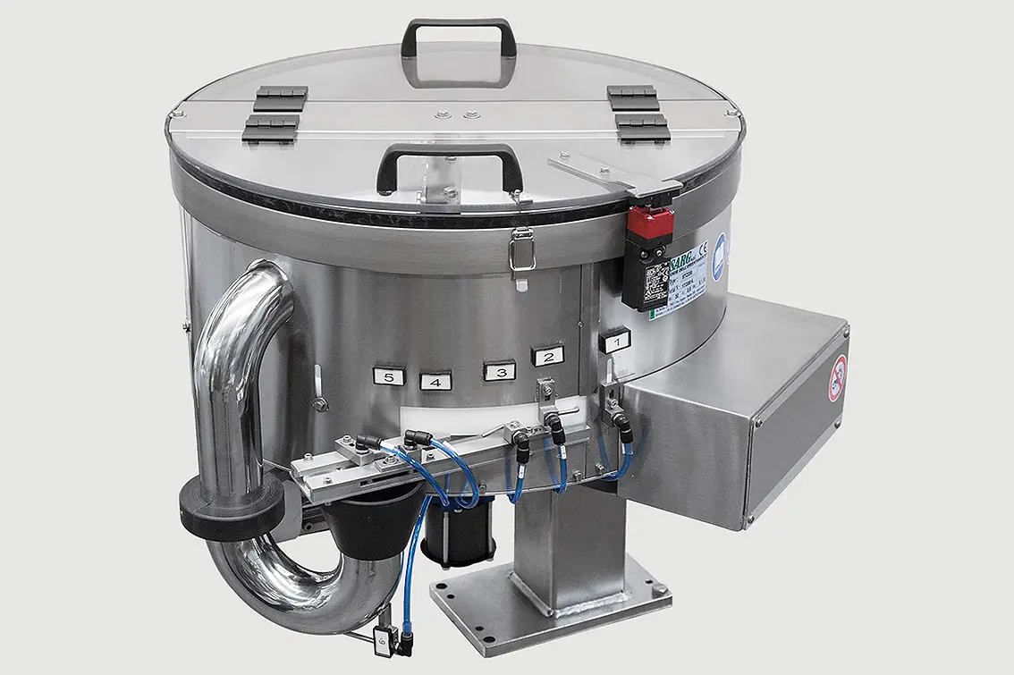
Bowl technology is only one decision. The pre-feed, outfeed, sensing, buffer, escapement and machine interface often determine whether the theoretical advantage becomes real output.
Compare both principles with identical production batches and all expected variants.
Count accepted orientation at the same discharge condition and interface tolerance.
Include replenishment, recirculation and downstream pauses—not only a short peak.
Every adjustment, jam clearance and rejected component affects real availability.
Check marking, wear, dust, static and damage after realistic repeated handling.
Review changeover, maintenance, spares, cleaning, noise and future format risk.
Vibratory tooling can solve complex orientation sequences by progressively checking the component as it climbs the bowl track. It may be a stronger choice where geometry is difficult, production rate is moderate or existing expertise favours vibratory handling.
Where many component formats, frequent product introductions or uncertain future geometry dominate the business case, a vision-guided flexible feeder may reduce dedicated tooling. Its complete cycle—including dosing, settling, image acquisition, robot picking and failed-pick recovery—must still meet the required output.
Compare centrifugal, vibratory, step and flexible feeder technologies →
Where selection remains uncertain, comparative trials should measure orientation yield, accepted rate, recirculation, component condition, changeover and recovery. The decision then follows visible evidence rather than a generic rule.
Prepare representative component samples →
Choose the simplest feeding architecture that proves the required sustainable output, component condition and production interface across the approved sample range.
No. Centrifugal systems are often selected for high-throughput applications, but sustainable accepted output depends on the component, tooling, lane count, buffer and downstream interface. Trials should compare the complete route.
Centrifugal feeders commonly operate with less process vibration and can be quieter, but total noise also depends on component collisions, hopper design, guarding, covers and outfeed transport.
A dedicated vibratory bowl can solve many complex orientation challenges. A centrifugal feeder can be excellent for repeat-volume parts with suitable geometry and demanding rates. Flexible or robotic feeding may be stronger where changeover breadth dominates.
Yes. When the selection boundary is uncertain, comparative trials using the same representative sample set and accepted-output definition can provide the most useful evidence.
Technical guide reviewed by Sortation Solutions · Updated 1 September 2026
Send a part photograph or drawing, required orientation, target sustained output and details of the receiving machine. We will define the right next step.
Share a photograph or drawing, required orientation and target rate. The Sortation Solutions team will help identify the strongest feeding route.