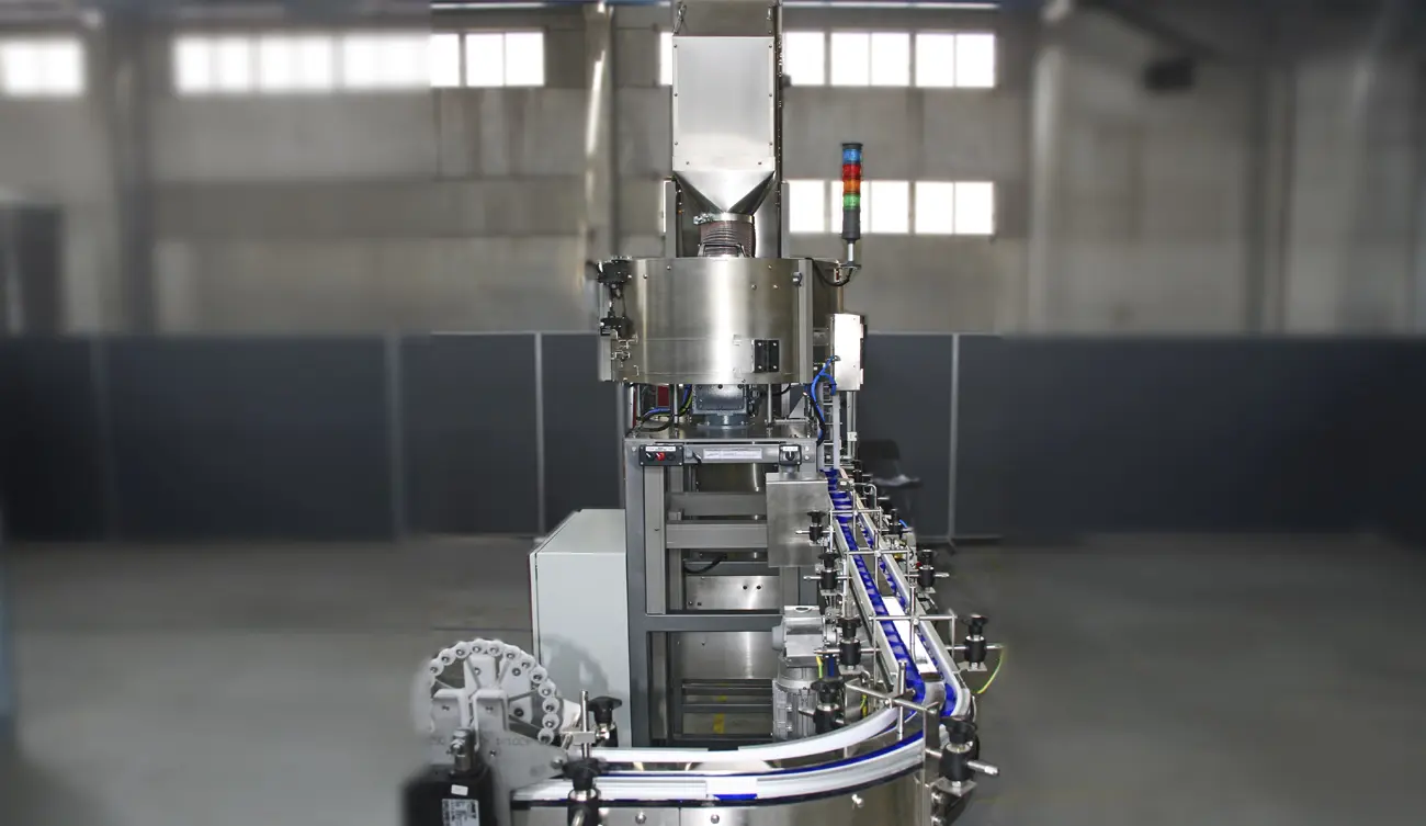
Centrifugal feeder
A controlled rotary disc separates components and moves them towards the perimeter for high-speed selection and orientation.
How centrifugal feeders work →Choose a centrifugal feeder by the accepted parts delivered in the required orientation at your receiving machine, not by bulk discharge alone. Review real component samples, sustained output, singulation and downstream hand-off before defining the feeder, tooling and accumulation route.
Reliable output depends on the complete route from bulk loading to one-part release. We coordinate the feeder, tooling, accumulation, sensing and downstream hand-off as one production system.
A controlled rotary disc separates components and moves them towards the perimeter for high-speed selection and orientation.
How centrifugal feeders work →A hopper or elevator regulates bowl level so the centrifugal bowl feeder runs consistently without flooding or starving.
Part-specific guides, selectors and recirculation reject incorrect presentations while protecting the component surface.
Track, conveyor or air transport creates controlled flow and a useful buffer between feeder and receiving machine.
One-part release, sensors and optional vision checks confirm presence and orientation at the machine interface.
Explore vision verification →Demand signals, level control, alarms, stop/restart logic and guarding are designed around operation and maintenance.
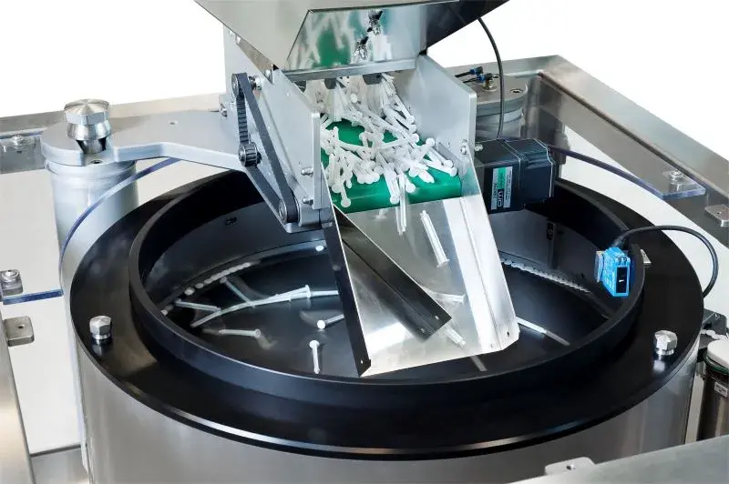
A centrifugal feeder can deliver rapid, smooth component movement without the repeated vibration of a conventional bowl. The best applications combine stable component geometry with a clear mechanical feature that can be selected at speed.
Centrifugal feeding is assessed against the real component, the full range of production variation and the condition in which the next process needs to receive it.
Orientating plastic closures, dispensing caps, lids and rings for capping, inspection or assembly.
Cap feeder applications →Separating lightweight components with controlled recirculation and surface-aware tooling.
Plastic parts feeding →Application-specific handling, cleanability and inspection for suitable healthcare components.
Medical feeder applications →Presenting clips, connectors, inserts and small engineered parts to assembly equipment.
Automotive feeder applications →High-flow presentation for suitable confectionery, wrapped and rigid food items.
Orientating pressings, fixings and formed parts where geometry supports rotary selection.
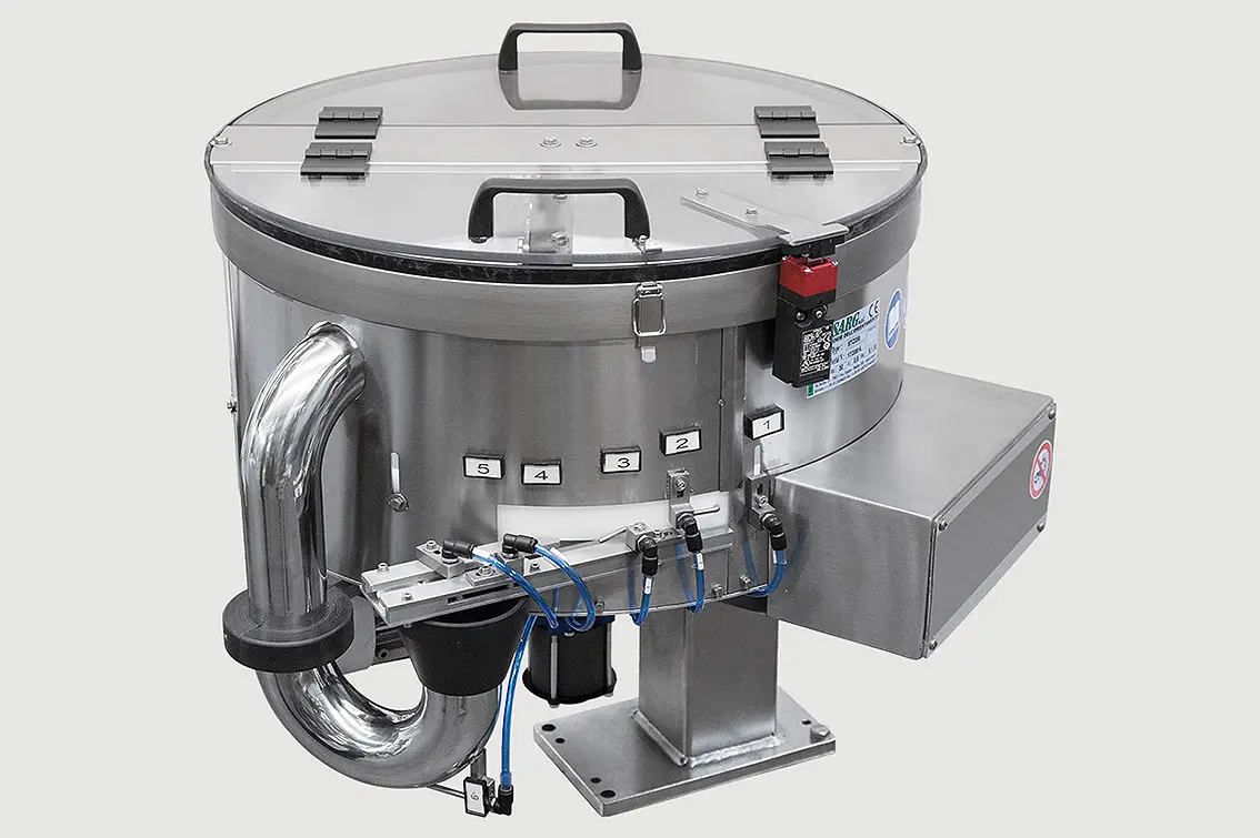
A high-speed parts feeder should be specified by sustainable accepted output—not simply the speed of its rotating disc. Orientation yield, track capacity, low-level recovery and the downstream machine all influence production performance.
Our project route defines the discharge condition, normal replenishment, test duration and permitted interventions before the final rate is agreed.
Correctly orientated parts available at the receiving-machine interface, at a sustainable rate, through normal production conditions.
Record every component, orientation, sustainable rate and machine interface.
Run representative parts to expose nesting, tangling, marking and natural variation.
Develop the feeder, tooling, buffer, sensors, controls and safeguarding as one scope.
Resolve the mechanical hand-off, signals, line logic, access and responsibilities.
Test agreed output, recovery, fault conditions and documentation before delivery.
Use focused buying and engineering guidance to understand terminology, application fit, cost drivers and the information needed for a robust specification.
Understand rotary feeder, centrifugal sorter, parts unscrambler and orientor terminology.
Understand unscramblers →Plan high-speed cap and closure orientation around geometry, variation and the capping-machine hand-off.
Review cap feeding →Assess moulded-part behaviour, static, interlocking, marking and representative sample requirements.
Review plastic parts →Plan bulk storage, singulation, orientation, accumulation and controlled machine release as one system.
Explore automatic feeding →Define face, leading feature, datum, pitch and the accepted presentation at the production hand-off.
Define component orientation →Verify visible orientation and quality features, then pass, recirculate or reject each component.
Review vision integration →See what drives centrifugal feeder cost and what a comparable production-system quotation should define.
Understand cost drivers →Capture approved parts, orientation, accepted output, interfaces, trials and FAT evidence.
Build the specification →Compare motion, speed, tooling, format flexibility and component suitability.
Compare feeder types →A centrifugal feeder uses a rotating disc and bowl wall to separate bulk components, move them towards the perimeter and present correctly orientated parts to an outfeed. It is commonly selected when a production line needs high, repeatable component flow.
A centrifugal feeder uses controlled rotary motion rather than a vibrating spiral track. It can be advantageous for high-rate applications, lower-noise operation and gentle handling, while vibratory bowls often suit a broader range of tooling challenges. Representative trials determine the better method.
Typical candidates include caps, closures, moulded plastic parts, medical components, electrical parts, metal pressings and other small components that can be separated and mechanically orientated. Part geometry, finish, variation and required discharge condition must be reviewed.
The sustainable rate depends on the component, orientation yield, number of lanes, replenishment, outfeed accumulation and receiving-machine behaviour. We define the rate as accepted parts delivered at the agreed discharge condition and prove it using representative samples.
Yes. The project can include hoppers, elevators, conveyor or track interfaces, sensors, escapements, vision checks, PLC signals, guarding and commissioning, subject to an interface review.
Send photographs or drawings, dimensions, material and finish, all component variants, the required orientation, target sustained rate, available space and details of the downstream machine. Representative samples are normally required before final specification.
Technical content reviewed by Sortation Solutions · Updated 1 September 2026
Start with the rate at which the receiving machine consumes accepted parts and the interruption it must tolerate. Convert that interruption into parts, then review usable track capacity and the rate needed to rebuild the buffer. This makes output comparisons more useful than a rotary speed or a short demonstration. The high-speed feeding guide includes an explicitly hypothetical calculation and the production transitions to demonstrate with real components.
Send a part photograph or drawing, required orientation, target sustained output and details of the receiving machine. We will define the right next step.
Share a photograph or drawing, required orientation and target rate. The Sortation Solutions team will help identify the strongest feeding route.