Store
A hopper or elevator provides useful autonomy without placing excessive component load into the orienting device.
Automate the complete route from mixed bulk components to a correctly orientated, demand-controlled hand-off at your production machine.
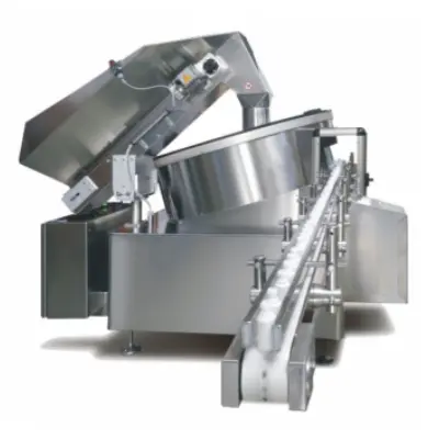
An automatic parts feeder receives randomly loaded components, separates them, rejects unsuitable presentations and supplies accepted parts in a repeatable orientation. The receiving machine then gets one part, or a defined group, when its control system requests it.
The feeder is not just the bowl. Reliable automation also depends on a regulated bulk supply, a stable outfeed, sufficient accumulation, sensing, an escapement and a clear control handshake.
Every stage must support the production target. A fast orienting bowl cannot compensate for unstable replenishment, inadequate accumulation or a slow release mechanism.
A hopper or elevator provides useful autonomy without placing excessive component load into the orienting device.
Level sensing regulates replenishment so the working population remains stable rather than flooding or starving the feeder.
Mechanical tooling, controlled motion or vision establishes a presentation the receiving process can use.
A track or conveyor creates a buffer between continuous feeder flow and an indexing production cycle.
An escapement isolates one component, controls spacing and prevents following parts entering the machine together.
Sensors and PLC logic manage demand, faults, safe stops, restart sequence and operator information.
“Automatic parts feeder” describes the result, not one machine type. The best technology follows from the physical part, production mix and required hand-off.
Strong candidate for stable components requiring rapid, smooth rotary separation and orientation.
Explore centrifugal feeding →Versatile dedicated tooling for components that respond well to controlled movement along a spiral track.
Quiet elevation and separation for suitable larger, heavier or surface-sensitive components.
Vision-guided robotic picking for higher format variety and lower dependence on dedicated orienting tooling.
Tracks and conveyors preserve orientation, create accumulation and deliver parts to the release point.
Machine vision or sensors verify visible features where mechanical orientation alone cannot prove the state.
Review vision verification →A parts feeder may supply a press, robot, assembly nest, test station, capping machine, inspection conveyor or packaging process. Each receiving operation needs a different datum, gap, orientation tolerance and release signal. Those requirements should be defined before the feeder outfeed is designed.
Nominal CAD dimensions do not show flash, oil, static, colour differences, warped mouldings, worn tooling or mixed production batches. Representative samples reveal whether components nest, tangle, overlap, mark or change behaviour after repeated recirculation.
Where several variants must use one system, the assessment should identify common features, format parts, recipe settings and line-clearance needs. A dedicated centrifugal feeder may suit a stable high-volume family; a flexible feeder may be more appropriate where change is frequent.
The accepted state should be described in measurable terms: which face is up, which end leads, the positional tolerance, available pitch and whether the part must be stationary or moving. The design must also state how the next machine requests parts and how both systems respond to a full track, blocked outlet, open guard or emergency stop.
Use an agreed test duration and count correctly orientated parts at the production hand-off. Record normal replenishment, rejects, operator interventions, stoppages and restart behaviour. This creates a defensible acceptance test and prevents an internal bowl-speed claim being mistaken for usable line output.
Send a clear part photo or drawing, dimensions, material, finish, all variants, required orientation, accepted parts per minute and the receiving-machine interface.
An automatic parts feeder takes components from bulk storage, separates them, establishes the required orientation and delivers them to a defined point for assembly, inspection or packaging. A complete system normally includes replenishment, an orienting device, an outfeed, sensing and a controlled release.
The answer depends on part geometry, surface, tendency to tangle, format variety, target rate and required presentation. Centrifugal, vibratory, step and vision-guided flexible feeders each suit different operating conditions, so selection should start with representative components.
Yes, subject to an interface review. The mechanical height and datum, available space, demand signal, accumulation, escapement, guarding and stop or fault behaviour must be agreed with the receiving machine.
Specify correctly orientated parts available at the agreed hand-off, over a stated test duration and using approved production samples. Peak movement inside the bowl is not the same as sustainable accepted output.
Provide part photographs or drawings, dimensions, weight, material, finish, all variants, required orientation, sustainable rate, available footprint and details of the receiving process.
Technical content reviewed by Sortation Solutions · Updated 1 September 2026
Send a part photograph or drawing, required orientation, target sustained output and details of the receiving machine. We will define the right next step.
Share a photograph or drawing, required orientation and target rate. The Sortation Solutions team will help identify the strongest feeding route.