Screw caps
Threaded plastic closures orientated open-side down or to the presentation required by the chute and capping head.
Sort and orient caps, lids and rigid closures for controlled presentation into automatic capping, inspection and assembly machinery.
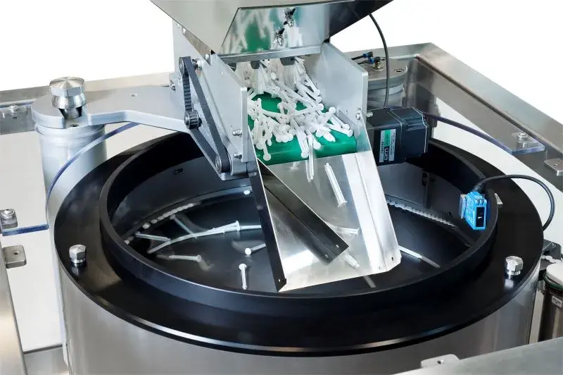
Loose caps are metered into a rotating bowl. The centre disc separates the bulk mass and moves closures towards perimeter tooling, where the required orientation is selected. Incorrectly presented caps are returned for another pass while accepted closures transfer to the capper chute, conveyor or placement system.
The engineering boundary includes more than the bowl: hopper supply, bowl level, track capacity, cap detection, capping-machine demand and stop/restart behaviour all affect line performance.
Rigid closures with repeatable features can be strong candidates for centrifugal feeding. More flexible or tangled formats need a wider technology comparison.
Threaded plastic closures orientated open-side down or to the presentation required by the chute and capping head.
Low-profile closures separated and selected using face, rim, liner or profile differences.
Protective caps and covers presented to placement, pressing, inspection or assembly operations.
Suitable rigid flip-tops, plugs and fitments reviewed for hinge, spout and open-side behaviour.
Annular packaging components orientated for insertion, assembly, inspection or counting.
Pumps, triggers and dip-tube assemblies require specific trials and may favour another feeder route.
The accepted result is a controlled reserve of correctly orientated closures available when the capping machine calls for them.
Hopper capacity and refill level are matched to the desired operator attendance interval.
Sensors regulate replenishment so the bowl remains productive without excessive cap pressure.
Mechanical selection and optional verification manage inverted or incorrectly presented closures.
Vision verification →Chutes, belts or air-assisted tracks preserve orientation between feeder and cap applicator.
A controlled buffer absorbs short capper pauses without compressing or damaging closures.
Full-track, low-level, run demand and fault signals coordinate the feeder with the line.
A closure can change between mould cavities, suppliers, colours, materials and batches. Liners, tamper features, flash, distortion and surface finish can all affect separation or selection. The approved sample set should represent the range production will actually use.
State whether the cap must arrive thread-down, open-side down, hinge-leading, face-up or in another controlled presentation. Also define the permitted rotation and the exact point at which orientation is accepted.
The useful rate is not the number circulating inside the bowl. Count correctly orientated caps at the capper interface under normal replenishment and demand. Record rejects, interventions, blocked chutes and recovery after short stops.
Where several caps share the system, identify change parts, tool-free adjustments, recipe settings, line-clearance points and verification checks. A fast feeder provides little value if changeover is slow or settings are difficult to reproduce.
See how the complete automatic feeding path connects to production machinery →
Send closure samples, a marked orientation image, target bottles per minute and the receiving capper details. This allows the feeder route and trial plan to be narrowed quickly.
A centrifugal cap feeder uses continuous rotary motion and closure-specific tooling to separate bulk caps, reject incorrect presentations and deliver correctly orientated closures to a capping, inspection or assembly process.
Potential applications include screw caps, flat caps, overcaps, dispensing closures, rings, plugs and suitable lids. Pumps, triggers and closures with flexible dip tubes may require a different feeding principle or specialist handling.
The sustainable rate is application-specific. Cap geometry, orientation yield, lane count, outfeed accumulation, capper demand and replenishment all affect accepted closures per minute.
A part family may be possible when the closures share suitable geometry and change parts or repeatable settings can control the differences. Each variant must be trialled and the changeover method defined.
Mechanical tooling can reject an incorrect presentation and optional sensors or vision can verify visible orientation before the cap reaches the application point. The inspection method depends on the closure and required assurance.
Send caps from multiple production batches and every cavity, colour, material, supplier or revision expected in use. Include normal flash, distortion, liner variation and the bottles or downstream interface where relevant.
Technical content reviewed by Sortation Solutions · Updated 1 September 2026
Send a part photograph or drawing, required orientation, target sustained output and details of the receiving machine. We will define the right next step.
Share a photograph or drawing, required orientation and target rate. The Sortation Solutions team will help identify the strongest feeding route.