Geometric selection
Rails, slots, ledges, wipers and guides use dimensions, centre of gravity and stable faces to accept one state.
Separate, align and verify components so the next assembly, inspection or packaging process receives the correct state every cycle.
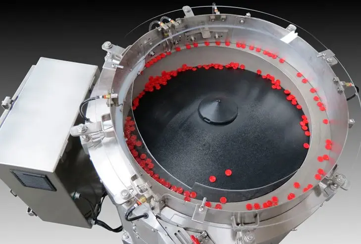
Component orientation means controlling a part’s attitude and direction from a random starting state. Depending on the process, the accepted result may be face up, a particular end leading, an axis aligned, a slot at a defined angle or a feature located against a datum.
A reliable orienting system separates parts first, identifies or exploits repeatable geometry, removes wrong states and preserves the accepted state through the final hand-off.
Mechanical selection is often fast and repeatable. Vision becomes valuable when the decisive feature cannot be proved reliably by contact tooling alone.
Rails, slots, ledges, wipers and guides use dimensions, centre of gravity and stable faces to accept one state.
Wrong presentations return without interrupting accepted flow or repeatedly damaging the component.
Directed air may separate, turn or reject suitable lightweight parts where contact tooling alone is insufficient.
Presence, height, colour, material or a simple feature can be checked with an appropriate industrial sensor.
Cameras inspect visible orientation, classify states and command rejection, recirculation or robotic picking.
See vision-assisted feeding →A robot can pick and place identified parts where format mix or complex attitude justifies flexible handling.
An annotated orientation brief protects the feeder supplier, machine builder and customer from interpreting the required presentation differently.
State which surface is up, down, inward or outward and whether the opposite face is visually similar.
Identify the end, thread, flange, tab, opening or datum that must lead in the direction of travel.
Define acceptable rotation around each relevant axis rather than asking for an undefined exact position.
State whether parts may touch, the minimum clear gap and the centre-to-centre spacing at release.
Identify the rail, belt, nest or stop against which the receiving machine locates the component.
Define what must be checked, what constitutes a reject and where rejected components go.
A centrifugal feeder uses rotary movement to separate components and drive them towards part-specific selection tooling around the perimeter. It is a strong candidate where geometry is stable, the required orientation can be recognised robustly and sustainable output is important.
A component can leave the bowl correctly and still rotate, tip, overlap or build damaging pressure before it reaches the machine. Track width, side guides, belt support, accumulation length, transitions and escapement geometry must preserve the state through every downstream stage.
Orientation confirms presentation. Quality inspection may check dimensions, colour, moulding defects, contamination or assembly features. One camera can sometimes perform both tasks, but each acceptance rule, image view, lighting condition and reject action should be specified separately.
Tooling should work across approved dimensional tolerances, cavity differences, suppliers, batches, colours and normal finish variation. Trial samples should include the difficult production condition, not only selected good parts. If the orientation feature changes between variants, define change parts or a different feeding route before design freeze.
A parts orientation system does four jobs: separates random bulk components, selects the required attitude, rejects wrong states and preserves the correct state until controlled release.
A parts orientation system converts randomly presented bulk components into a repeatable position and attitude that a downstream machine can accept. It may use mechanical tooling, controlled motion, sensors, machine vision or a combination of methods.
Singulation separates components so they can be handled individually. Orientation controls which face, end, axis or feature is presented. A production system often needs both functions before release.
Vision can identify visible orientation and direct a reject, recirculation device or robot. It does not automatically solve separation, part presentation, hidden features or unstable overlap, so lighting, part spacing and reject logic remain important.
Use an annotated drawing or photographs showing the accepted state, datum features, angular or positional tolerance, direction of travel, pitch and final release condition. Avoid relying only on descriptions such as right way up.
Sometimes. The answer depends on shared geometry, tooling changes, recipe control and how completely the previous format must be cleared. Representative trials should cover every approved variant.
Technical content reviewed by Sortation Solutions · Updated 1 September 2026
Send a part photograph or drawing, required orientation, target sustained output and details of the receiving machine. We will define the right next step.
Share a photograph or drawing, required orientation and target rate. The Sortation Solutions team will help identify the strongest feeding route.