Present
Feeder tooling and the outfeed create a controlled face, height, position and gap.
Verify visible orientation and quality features after centrifugal feeding, then pass, recirculate or reject each component through controlled line logic.
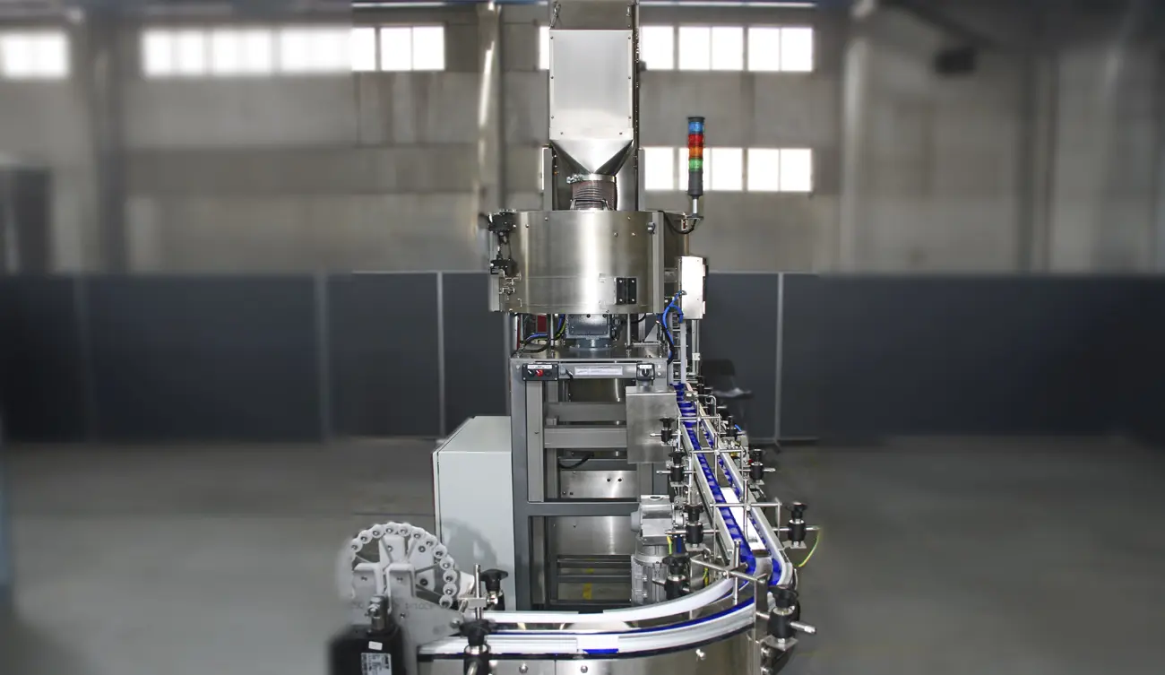
Machine vision checks the image of each presented component against defined rules. In a centrifugal feeding system it can confirm orientation, identify visible variants or defects and command a reject or recirculation device before the part reaches the production hand-off.
The camera works only as well as its presentation. Parts must be separated, stable, in focus and illuminated so the required feature is consistently visible across normal production variation.
A stable inspection result depends on part presentation, optics, lighting, decision logic and physical rejection as one engineered chain.
Feeder tooling and the outfeed create a controlled face, height, position and gap.
Backlight, ring, diffuse or directional lighting makes the relevant feature repeatably visible.
Lens, working distance, exposure and trigger timing freeze the component at useful resolution.
Rules distinguish accepted orientation, known variants, rejects and uncertain results.
The PLC tracks the part to an air jet, diverter, stop gate or recirculation point.
Reject confirmation, blocked-path sensing and counts show that the physical action occurred.
“Check the part” is not a specification. Each feature needs an accepted state, a worst-case sample and a response when the result is uncertain.
Identify which face is visible when two mechanically stable states otherwise appear similar.
Confirm a slot, flange, thread, opening or other end feature is leading correctly.
Identify an approved colour or distinguish visible format features, subject to controlled lighting.
Check that a defined insert, ring, seal or visible component is present in the field of view.
Inspect presence or position of a visible code, symbol or print where resolution allows.
Detect a defined visible shape or surface failure using approved good and reject boundaries.
The most robust high-speed route often uses mechanical tooling to remove obvious wrong states and vision to verify the final visible feature. This reduces image complexity, protects inspection time and prevents the camera becoming responsible for uncontrolled overlap or random presentation.
A real image can be affected by contamination, reflections, component variation, motion blur or partial obstruction. The system should distinguish a confirmed pass from fail and no-read conditions. The customer must decide whether a no-read is rejected, recirculated or stops production.
When the camera and reject device are separated, the PLC must track the inspected component reliably. The reject path should prevent bounce-back and include confirmation where a missed reject would create product or process risk. A reject-bin full sensor, lockable access or reconciliation may also be required.
Commissioning should include every approved format, normal colour and finish variation, borderline conditions and known defects. Artificial samples can help develop a concept, but final acceptance rules should reflect actual production parts and the customer’s quality decision.
Basic systems may provide only pass, fail and fault signals. More detailed scopes can retain counts, reject categories, images, recipe versions or batch references. Data ownership, retention, user access, time synchronisation and higher-level interfaces need explicit definition.
Machine vision can verify only features visible with the agreed view, lighting, resolution and component presentation. It should not be described as checking hidden or unspecified defects.
Vision can verify a visible orientation feature that mechanical tooling cannot distinguish reliably, inspect defined attributes and stop or reject an incorrect part before it reaches the next process.
Usually not. Parts still need controlled separation, spacing and presentation so the camera receives a consistent image. Mechanical pre-orientation often reduces the number of states the vision system must handle.
Depending on image view, lighting, resolution and component presentation, it may check orientation, presence, colour, printed marks, shape, assembly features or defined surface conditions. Capability must be proved with representative good and reject samples.
A failed part may be blown off, diverted, recirculated or stopped at a controlled reject station. The design should prevent rejected parts re-entering accepted output unless that route is intentionally validated.
Yes, where specified. The control scope can include counts, reject categories, images, batch information or interfaces to higher-level systems. Retention and traceability requirements must be agreed before design.
Technical content reviewed by Sortation Solutions · Updated 1 September 2026
Send a part photograph or drawing, required orientation, target sustained output and details of the receiving machine. We will define the right next step.
Share a photograph or drawing, required orientation and target rate. The Sortation Solutions team will help identify the strongest feeding route.