Hopper or elevator
Maintains an appropriate bowl level without flooding, starvation or excessive part pressure.
Separate, orient and deliver repeat-volume components using smooth rotary motion engineered around the real part and machine interface.
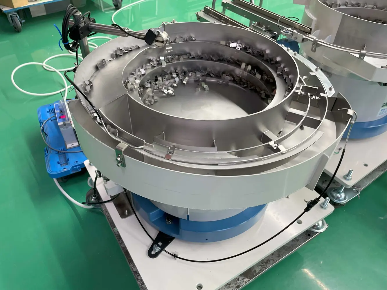
A rotary parts feeder is a high-throughput component handling machine that uses rotating motion to spread bulk parts, select the correct presentation and deliver accepted components to a track, conveyor or escapement.
The same equipment may be described as a centrifugal parts unscrambler, rotary sorter or orientor, particularly when the emphasis is on converting random bulk parts into ordered flow.
The term is frequently used alongside centrifugal feeder and rotary bowl feeder. What matters is not the name alone, but whether the disc, bowl, tooling and discharge route can produce the required sustainable output without damaging the component.
Different rotary arrangements solve different presentation problems. Final selection follows from trials, required orientation and the receiving process.
| Configuration | How it handles parts | Typical selection boundary |
|---|---|---|
| Flat-disc rotary feeder | Spreads parts from a rotating disc towards an outer discharge route. | Useful where separation and high flow are more important than complex manipulation. |
| Dual-motion centrifugal feeder | Centre disc and outer bowl can be controlled independently to manage flow and selection. | Strong candidate for high-rate orientation using repeatable component features. |
| Pocket or scallop feeder | Supports cylindrical or unstable parts in defined carriers around the feeder perimeter. | Considered when parts need extra support to preserve presentation at speed. |
| Multi-lane rotary system | Divides accepted parts across parallel discharge paths. | Used where one lane cannot supply the required accepted rate or several processes need feed. |
A productive rotary feeder depends on every stage before and after the bowl. Treating it as one integrated system protects output and recovery.
Maintains an appropriate bowl level without flooding, starvation or excessive part pressure.
Disc speed, bowl speed and surface condition create stable component circulation.
Selectors accept the required state and return incorrect presentations for another pass.
Track or conveyor capacity buffers normal variation between feeder and receiving machine.
Presence, level, blockage and optional orientation checks provide useful machine feedback.
Start, stop, restart and fault logic coordinate the feeder with the complete production line.
Rotary feeding is normally considered when component demand is high, geometry is reasonably consistent and a robust feature can distinguish the correct orientation. Caps, closures, rings, discs and repeatable moulded parts are common starting points, but no category guarantees success.
Specify accepted parts per minute at the real machine interface. State the test duration, replenishment method, component variants, permitted interventions and downstream demand pattern. This separates a defensible production rate from a short unloaded peak.
Material choice, contact surfaces, recirculation path, bowl loading and differential speeds all influence marking. Trials should include normal production parts and enough running time to expose repeated contact, dust generation, edge wear or cosmetic damage.
A rotary feeder is often attractive for high flow, smooth movement and lower-vibration operation. A vibratory bowl may offer more freedom for complex tooling or lower-rate applications. Compare the complete system and prove the boundary with real samples.
Compare centrifugal, vibratory, step and flexible feeders →
Select the machine from accepted output, component condition and hand-off performance—not from the largest claimed bowl speed.
A rotary parts feeder uses continuous rotating motion to separate bulk components, move them towards an outer track and deliver parts in a controlled orientation. It is commonly used where a production machine requires a high and repeatable component supply.
In component handling, rotary parts feeder, rotary bowl feeder and centrifugal feeder are often used for the same general feeding principle. The exact machine may use a flat disc, independently driven disc and bowl, or part-supporting pockets, so the required configuration should still be defined.
There is no reliable universal rate. Sustainable output depends on part geometry, orientation yield, track capacity, lane count, accumulation and the receiving-machine cycle. The rate should be proven with representative components at the agreed hand-off point.
Typical candidates include caps, closures, moulded plastic parts, rings, discs, small pressings and other repeatable components that separate cleanly and have a feature that tooling can use for orientation.
Multiple discharge lanes can be considered where component behaviour, bowl capacity and downstream interfaces support them. Each lane needs adequate selection, accumulation, sensing and demand control.
Provide representative samples, drawings, all variants, required orientation, accepted parts per minute, receiving-machine details, outlet height, available footprint and the production environment.
Technical content reviewed by Sortation Solutions · Updated 1 September 2026
Send a part photograph or drawing, required orientation, target sustained output and details of the receiving machine. We will define the right next step.
Share a photograph or drawing, required orientation and target rate. The Sortation Solutions team will help identify the strongest feeding route.