Clips and retainers
Assess interlocking, spring behaviour, sharp features and the datum required for automated insertion.
Orient clips, connectors, washers, fasteners and moulded parts around the real variant range, required rate and assembly-machine hand-off.
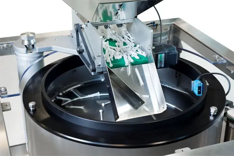
Bulk parts enter a feeder selected for their geometry and production rate. The system separates and orientates each component, preserves that state through an outfeed and releases it to an assembly nest, robot, insertion tool or inspection station when requested.
Centrifugal feeding is considered where a stable component family needs rapid, smooth flow. Difficult tangling, heavy parts, frequent unrelated variants or sensitive surfaces may favour another feeder type.
Automotive components often include cavity, supplier, coating and revision differences. The sample set must represent these variations before tooling is frozen.
Assess interlocking, spring behaviour, sharp features and the datum required for automated insertion.
Control keyed faces, latch features, delicate edges and presentation to assembly or test equipment.
Separate flat parts, prevent face-to-face overlap and identify directional features where present.
Define head, thread or shank leading and manage oil, swarf, burrs and tooling wear.
Account for static, flash, warped parts, cosmetic surfaces and variation between mould cavities.
Plastic parts guidance →Orient protective caps, plugs and sealing components for assembly, fitting or inspection.
The accepted component must arrive in the right state, at the right time and with enough buffer to protect the line from normal cycle variation.
An escapement isolates and transfers one component against the datum used by the assembly tool.
A defined pick point, stable pose and part-present signal support repeatable robotic handling.
Release timing, location and confirmation are coordinated with the press or installation cycle.
Visible orientation or features can be verified before the component reaches assembly.
Inspection integration →Components arrive at the correct datum and spacing for dimensional, electrical or presence testing.
Demand-controlled accumulation decouples continuous orientation from indexing machine cycles.
A centrifugal feeder is attractive where speed, smooth movement and relatively low vibration are important. Vibratory bowls, step feeders and flexible vision feeders remain valid options when geometry, tangling, weight, product mix or changeover points elsewhere. The parts feeder selection guide compares these routes.
Metal components should be trialled in the condition in which they reach production. Residual oil can change friction and carry contamination onto tooling. Burrs and sharp edges can catch guides, mark other parts and accelerate wear. These effects are missed when a trial uses specially cleaned or selected samples.
For each variant, define the format tooling, stored settings, component identification and line-clearance method. Consider parts trapped in the hopper, bowl, return path and outfeed. If a mixed component could reach the wrong assembly, add detection or a controlled verification step.
The orienting device normally runs continuously while assembly indexes. A correctly sized buffer absorbs that difference. Full-track sensing slows or pauses the feeder; low buffer triggers replenishment or a controlled machine response before the process starves.
Count accepted components at the agreed pick, nest or release position for a stated duration. Run all variants and normal replenishment, then test full buffer, blockage, guard opening, stop and restart. Record misfeeds, jams, damage, interventions and recovery time.
Provide real production samples from more than one batch, an annotated orientation drawing, assembly-cycle data and photographs of the proposed hand-off area.
Potential candidates include suitable clips, connector bodies, washers, rings, inserts, caps, fasteners and moulded parts. Geometry, oil, burrs, tangling, surface condition and required orientation determine the actual feeding route.
Sometimes, if the variants share stable handling and orientation features. Change tooling, recipe settings, format identification and line clearance must be defined, and every approved variant needs representative testing.
Count accepted parts at the agreed machine hand-off over a stated duration using representative production samples. Record jams, misorientation, marking, operator interventions, replenishment and stop or restart behaviour.
Yes. The system can present parts to an escapement, nest, conveyor pocket, robot pick point, insertion tool or inspection station, subject to agreed mechanical, control and safety interfaces.
Use parts in their normal production condition. The trial evaluates sliding behaviour, contamination transfer, edge catching, tooling wear, part-to-part contact and cleaning needs before the final design is confirmed.
Technical content reviewed by Sortation Solutions · Updated 1 September 2026
Send a part photograph or drawing, required orientation, target sustained output and details of the receiving machine. We will define the right next step.
Share a photograph or drawing, required orientation and target rate. The Sortation Solutions team will help identify the strongest feeding route.