Geometry
Asymmetry, openings, rims, bosses and other features may support mechanical orientation.
Separate and orient injection-moulded parts for assembly, insertion, inspection, counting and automated packaging processes.
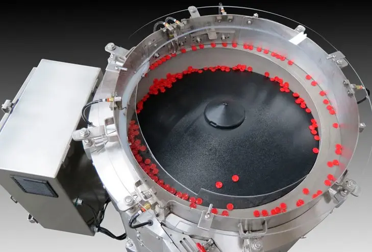
Rigid moulded components are strong starting candidates when they separate cleanly, have a repeatable centre of gravity and include a feature that can identify the required orientation. Examples include housings, clips, inserts, plugs, rings, caps and small packaging components.
Dimensions alone do not prove feedability. Real trials must expose static, flash, warpage, nesting, interlocking and cosmetic marking across normal production variation.
A useful assessment combines the drawing with bulk behaviour and the downstream presentation tolerance.
Asymmetry, openings, rims, bosses and other features may support mechanical orientation.
Natural resting positions influence how the component separates and approaches selectors.
Lightweight parts may cling, overlap or resist controlled transfer between surfaces.
Open features, hooks and flexible sections can interlock within the bulk mass.
Gloss, texture, colour and cosmetic requirements affect contact materials and recirculation.
Cavity, flash, warpage, material and supplier differences must be included in the sample set.
Orientation is defined at the interface: position, rotation, spacing and availability must match the next automated operation.
Present parts to nests, indexing tables, insertion tools or robotic pickup points.
Automotive applications →Control spacing and presentation for dimensional, cosmetic, code or feature checks.
Vision inspection →Feed components into cartoners, wrappers, baggers, trays or counting systems.
Create a defined pickup position or controlled stream for automated handling.
Separate parts into a measurable stream for kits, bags, boxes or process demand.
Supply moulding, machining or secondary operations with a repeatable part orientation.
Freshly selected samples can hide the variation that causes production faults. Include parts from every mould cavity, more than one batch and each material, colour, supplier or revision. Clearly separate known defects so trial results are not distorted.
If the surface is visible to the customer, agree what marking, scuffing, dust or edge wear is acceptable. Inspect parts after realistic recirculation time. Contact materials and handling speeds can then be evaluated against a defined standard.
Low-mass plastic parts can respond to static charge, airflow and humidity. The engineering review should consider earthing, material pairing, ionisation, covers and local air assistance only where the trial evidence supports them.
A feeder may handle several related mouldings, but every format needs an accepted setup and rate. Record change parts, adjustments, recipes, line-clearance steps and verification checks so changeover remains repeatable.
For healthcare products, also define contact materials, cleaning, evidence and validation boundaries. Read the medical component feeder guide.
Prove stable feeding across normal part variation while preserving the agreed surface condition and downstream presentation.
Yes, many rigid and repeatable moulded parts are potential candidates. Suitability depends on geometry, weight, symmetry, static, surface finish, nesting, tangling and whether tooling can reliably identify the required orientation.
Contact materials, disc surface, part loading, recirculation, tooling edges and differential speed are selected to limit marking. Representative trials should inspect components after repeated circulation, not only after one pass.
Static can make lightweight plastic parts cling, overlap or behave inconsistently. The system review can consider material contact, earthing, humidity, ionisation and airflow where appropriate.
They may be able to, but every cavity and production source should be represented in trials. Small dimensional differences, flash, warpage or surface texture can change orientation performance.
Mechanical selection normally returns incorrect presentations to the recirculation path. Optional sensing or vision may be added where a visible feature needs verification before release.
Highly flexible, tangled, fragile, heavily static, cosmetically critical or widely varying parts may favour vibratory, step, flexible or robotic feeding. Trials establish the strongest route.
Technical content reviewed by Sortation Solutions · Updated 1 September 2026
Send a part photograph or drawing, required orientation, target sustained output and details of the receiving machine. We will define the right next step.
Share a photograph or drawing, required orientation and target rate. The Sortation Solutions team will help identify the strongest feeding route.